
How to Install The AR-15 Lower Parts Kit
Posted by Gun Builders Depot on May 7th 2020
Finished cutting and drilling your 80% lower receiver? Or, bought a stripped lower? Then congratulations! You're the proud owner of an AR-15 (well, at least legally). It doesn't look like much yet, and that's because you still need to assemble the thing. We're going to show you how with easy-to-follow written and picture instructions! No experience is required.
Time required: You'll need about an hour (60 minutes) to complete this install. There's also an important set of tools that are required or recommended:
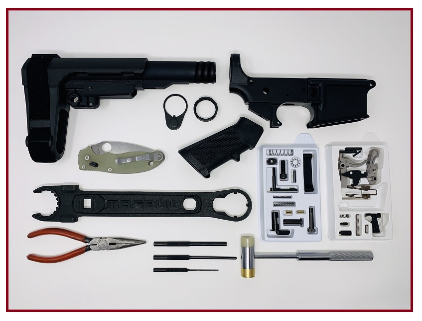
Parts Required
- Lower Parts Kit
- Lower Receiver
- Castle Nut
- Latch Plate
- Buffer Tube
Some parts kits do not come with a castle nut or latch plate, and most do not come with a buffer. These additional parts will be required for completing the install and final assembly of your rifle or pistol.
Tools Required
- Roll Pin Punches
- Gunsmithing Hammer
- Armorer's Wrench
- Needlenose Pliers
- Small blade or Knife
- Firearm Lubricant
- Masking Tape
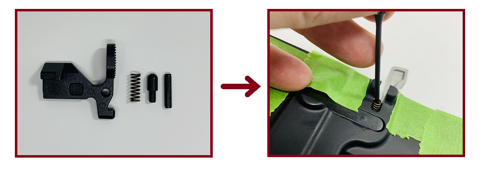
Lower Parts Kit Diagram
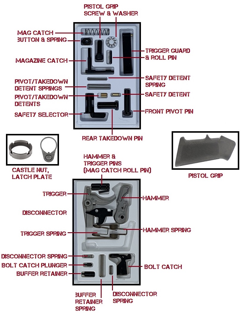
Before getting started, make sure you have all the parts shown in the lower parts kit diagram. If you're missing a pin, spring, or part, you'll have to pause your install. We're using the Anderson Stainless LPK. It's a truly quality kit that's very affordable. If you want to use the same kit, you may find it here.
Step 1: Trigger Spring Install
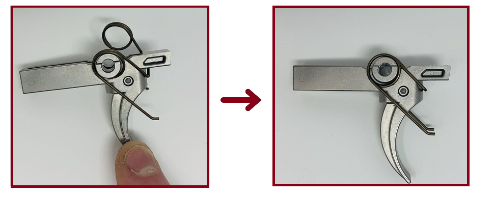
Install the trigger spring onto the trigger.
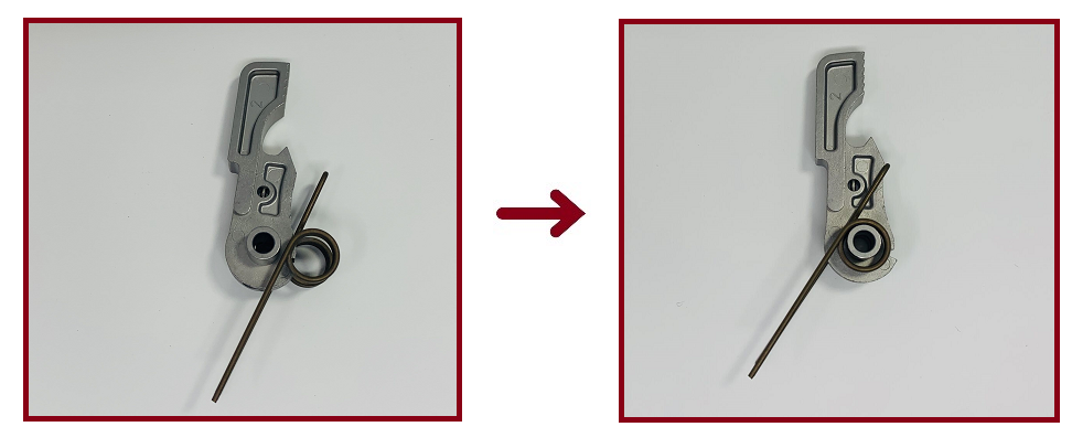
Step 2: Disconnector Spring Install
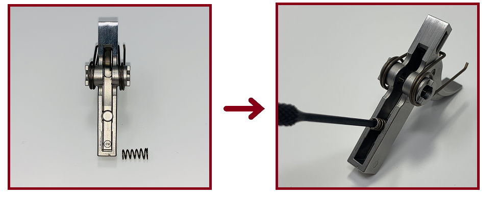
Install the disconnector spring onto the trigger. The wide end of the spring goes into the trigger. A punch helps get it seated.
Step 3: Hammer Spring Install
Install the hammer spring onto the hammer.
Step 4: Install Trigger and Disconnector
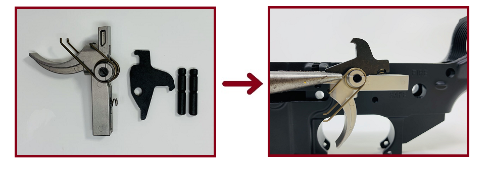
Insert the disconnector onto the trigger. Make sure the disconnector spring rides in the notch on the disconnector.
Insert the trigger and disconnector into the lower receiver. Press down on the top of the disconnector to align the pin holes. Gently tap the trigger pin into the receiver from the left side. The end of the pin without small grooves should go in first. Use lubricant, a punch, and the hammer to assist with the pin install.
Ensure the trigger pin is flush with the exterior walls of the receiver. The trigger spring's ends should face the magazine well.
Step 5: Install Hammer
Use the same punch, hammer, and lubricant to install the hammer and hammer pin. Ensure the ends of the hammer spring face the rear of the receiver. The spring ends should rest atop the trigger assembly.
Check the function of the hammer, trigger, and disconnector:
- Press down on the hammer. The trigger should keep the hammer cocked.
- Squeeze the trigger. The hammer should release. Keep a finger on the hammer so it doesn't hit the receiver.
- While squeezing the trigger, press the hammer back down. The disconnector should catch the hammer.
- Release the trigger. You should hear a "pop" as the disconnector hands the hammer off to the trigger.
- The hammer should remain cocked once the trigger is released.
Step 6: Install Trigger Guard
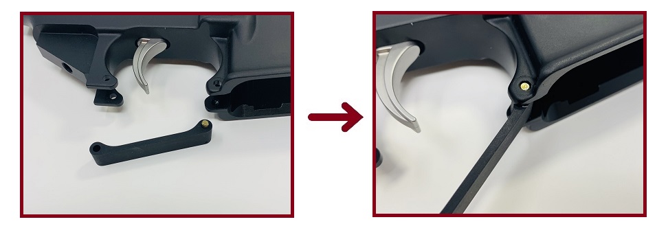
Insert the trigger guard's end with the spring-loaded brass pin into the two front trigger guard tabs.
Support the rear tabs for the trigger guard so they don't break during this next step. Align the other end of the trigger guard with the rear tabs. Using a 5/32" punch and hammer, tap the trigger guard roll pin into the tabs until the pin is flush on either side.
Step 7: Install Magazine Catch
Install the magazine catch. Lay the receiver flat on the left side and support the catch face so the threaded end of the catch protrudes on the right side of the receiver.
On the receiver's right side, put the magazine catch spring over the threaded end of the catch. Press down on the spring with the magazine release button and thread the button onto the threads until it hits the receiver.
Flip the receiver over. Press the magazine release button in as far as possible, pushing the magazine catch back out. Rotate the magazine catch clockwise three to four times. Align the catch with its channel and release the button. The catch should rest inside its cut-out cannel on the left right of the receiver. The button should be just resting under the surface of the receiver on the right side. Perform a function check of the magazine catch and release button by inserting and removing an empty magazine.
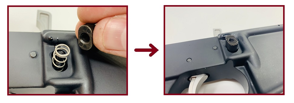
Step 8: Install Bolt Catch
Tape the receiver to prevent scratching it in this next step. Insert the bolt catch spring and plunger into the hole just above the magazine catch.
Using a punch and hammer, partially tape the bolt catch roll pin into the first hole on the bolt catch housing.
Press the bolt catch into the housing and maintain pressure to align the holes for the pin. Continue tapping the roll pin through the bolt catch housing until it is flush on both sides.
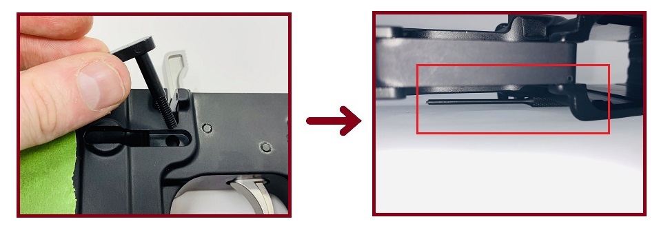
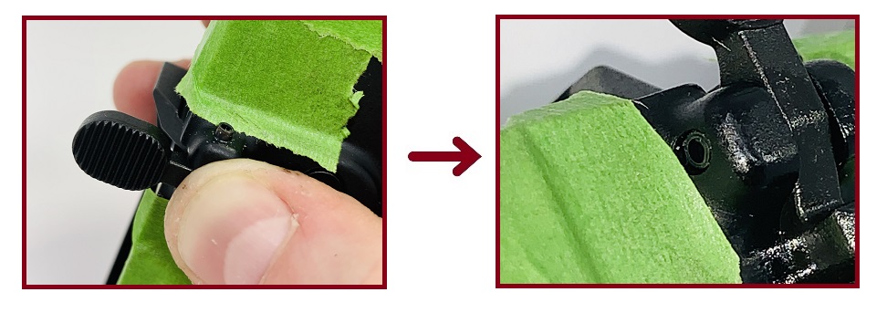
Step 9: Install Front Pivot Pin
Insert the front pivot pin's detent spring into the small hole on the right side of the receiver, immediately next to the pivot pin hole.
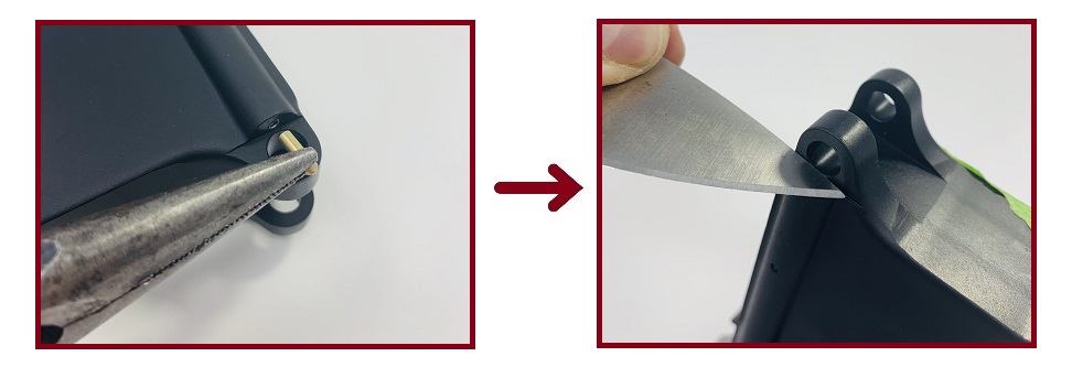
Press the pivot pin detent over top the detent spring. You will need to keep the detent compressed with a small blade or knife while you insert the pivot pin.
While keeping the detent compressed, slide the pivot pin into its housing. A channel cut into the pin will capture the detent once the pin is fully seated.
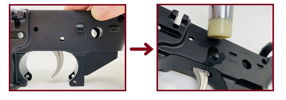
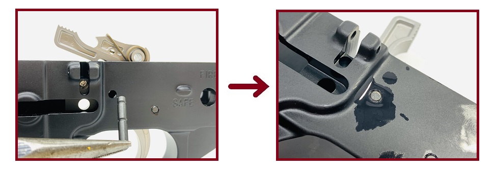
Step 10: Install Safety Selector and Pistol Grip
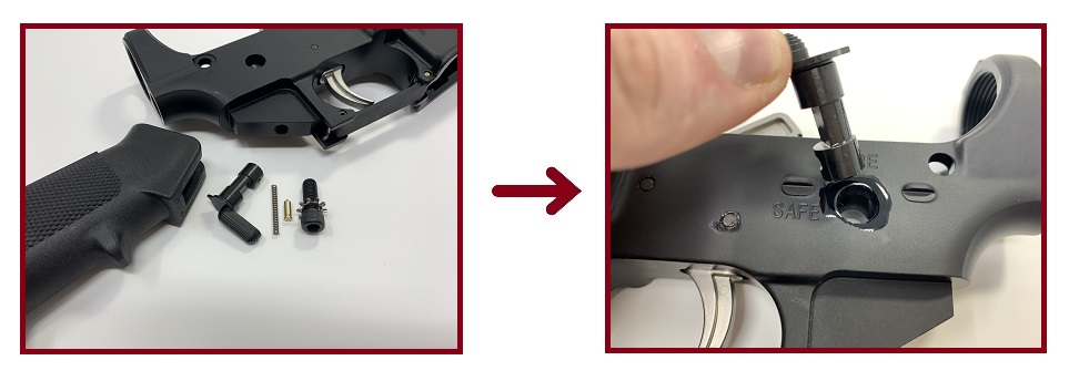
Insert the safety selector lever into the left side of the receiver next to the FIRE and SAFE engravings. It is a tight fit. Lubricant helps.
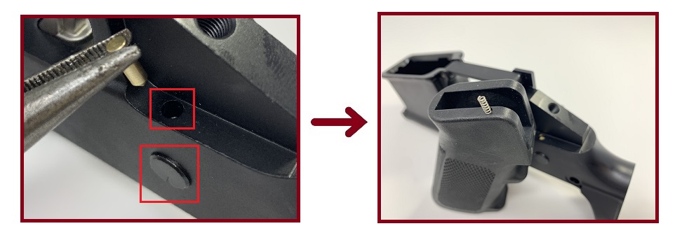
With the safety lever fully inserted, flip the receiver upside down. Drop the safety lever detent into its hole next to the pistol grip mount. Insert the safety lever detent spring into the small hole cut into the top of the pistol grip.
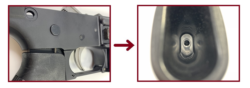
Insert the pistol grip onto the pistol mount. Ensure the safety lever detent spring aligns with the detent to capture it. The pistol grip should align with the threaded hole on the mount.
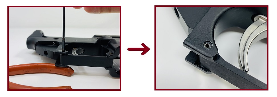
Install and tighten the pistol grip bolt and washer. Hand-tighten the bolt. The washer will ensure the pistol grip bolt does not loosen when the AR-15 is fired. Over-tightening the bolt could crack the receiver's aluminum.
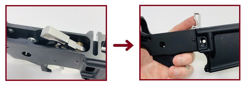
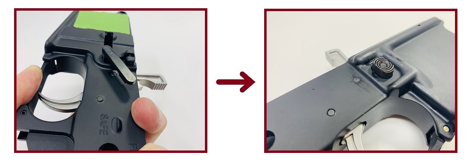
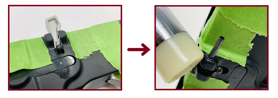
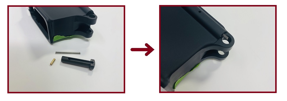
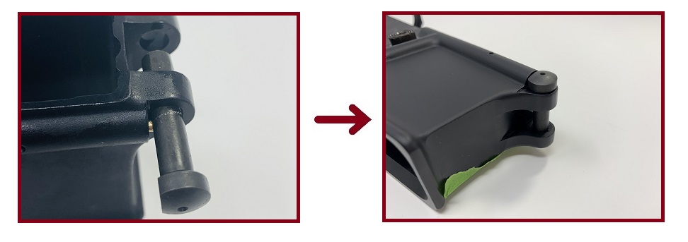
Step 11: Install Rear Takedown Pin
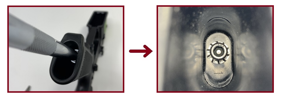
Insert the rear takedown pin detent into the small hole at the rear of the receiver, underneath the buffer tube housing.
Insert the rear takedown detent spring in the same hole. Collect the buffer tube, castle nut, and latch plate and thread the castle nut onto the buffer tube. Slide the latch plate over the tube's threads so it rests against the castle nut.
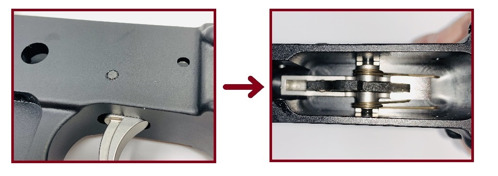
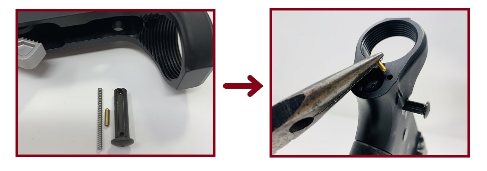
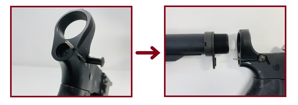
Step 12: Install Buffer Retainer and Buffer Tube
Partially thread the buffer tube into the buffer tube housing. Insert the buffer tube retainer spring into the hole drilled into the buffer tube housing's threads.
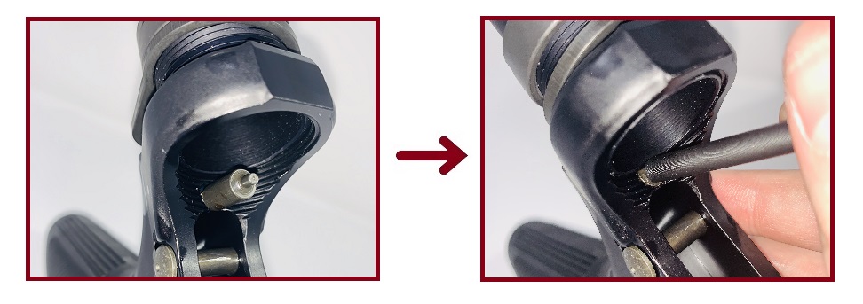
Insert the buffer retainer over top the retainer spring. A large punch helps to press the retainer down. With the retainer compressed, hand-tighten the buffer tube until it meets the retainer, capturing it inside the hole.
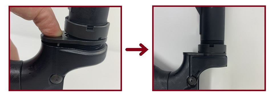
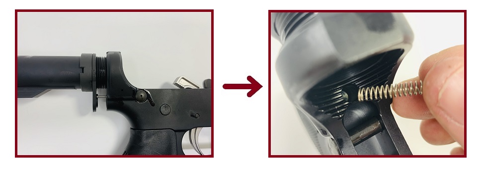
While hand-tightening the buffer tube, ensure the latch plate compresses the rear takedown detent spring into its hole. Keep the latch plate pressed down and tighten the castle nut until the nut secures the latch plate against the rear of the receiver.
Step 13: Tighten Buffer Tube with Wrench
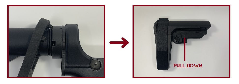
The buffer tube needs to be torqued so it doesn't loosen when the AR-15 is fired. Use an Armorer's Wrench to tighten the castle nut. You may need to remove the buttstock or pistol brace from the buffer tube to slide the wrench over the castle nut. Using Loctite or staking the castle nut will help to prevent the nut from loosening.
Your LPK Install is Finished
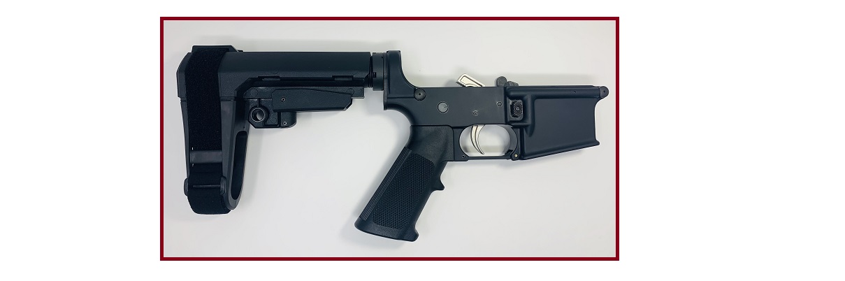
You LPK installation is complete. Depending on the lower parts kit you purchased for your assembly, certain components may need to "break in". During the break-in period, your trigger may feel heavy or gritty, and springs will feel snappy until they're conditioned. If you notice any of the issues below, try the troubleshooting steps below.
Troubleshooting the Parts Kit
The trigger won't reset.
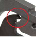
If the trigger fails to reset after firing a round, the hammer may be failing to release from the disconnector. This is a very common occurrence, especially with newly installed LPKs. Open the receiver and visually inspect the backside of the hammer, and the top of the disconnector.
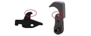
The two surfaces circled in red may need light polishing. If the hammer or hook on the disconnector suffer from small machining marks or metal burs, the hammer may get stuck when it should normally release.
When polishing the hammer and disconnector, take very small steps. Removing too much material could cause the disconnector and hammer to fail entirely. If the problem still isn't remedied with light polishing here, check the orientation of the disconnector spring next.
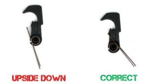
If the disconnector spring is oriented upside down, the spring may not be seated correctly, and/or it may be failing to operate the disconnector correctly. Ensure the skinny end of the spring is facing the disconnector notch. If the spring is oriented correctly, move onto the next possible issue:
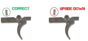
The hammer spring may not be oriented correctly. If it was installed upside down, it will fail to provide the correct force required for the hammer to strike and reset appropriately. If the hammer spring is oriented correctly, the hammer and/or trigger pins may be at fault.
The hammer and trigger pins could have small burs or imperfections that would cause the trigger or hammer (or both) to bind or operate poorly. This can throw off the timing of the receiver when the AR-15 functions, resulting in the hammer and trigger failing to reset.
DISCLAIMER: If you are new to the world of DIY gun building, you likely have a lot of questions and rightfully so. It’s an area that has a lot of questions that, without the correct answers, could have some serious implications. At GunBuilders.com, we are by no means providing this content on our website to serve as legal advice or legal counsel. We encourage each and every builder to perform their own research around their respective State laws as well as educating themselves on the Federal laws. When performing your own research, please be sure that you are getting your information from a reliable source.